
- MKTG45601 /MKTG45621 Strategic Global Marketing Assignment Brief 2026 | NTU
- CIPD Level 7 Advanced Diploma in Strategic Learning and Development (610/3538/5) Assessment Brief 2026
- UNIT CMI 525 Using Reflective Practice to Inform Personal and Professional Development Assessment Brief 2026
- CIPD Level 5 Associate Diploma in People Management Assessment Overview 2026
- NCFE Level 4 Unit 5 Organisational Data (J/651/0928) Assignment Brief 2026
- NCFE Level 4 Unit 04 Stakeholder Engagement and User Experience in Data Analytics (H/651/0927) Asignment Brief 2026
- ATHE Level 3 Unit 4 Working in Health and Social Care (K/618/4170) Assignment Example 2026
- ATHE Level 3 Unit 3 Human Growth and Development (T/618/4169) Assignment Example 2026
- ATHE Level 3 Unit 2 Principles, Values and Regulation in the Health and Social Care Sector (M/618/4168) Assignment Example 2026
- ATHE Level 3 Unit 1 Structure and Overview of the Health and Social Care Sector (K/618/4167) Assignment Example 2026
- NCFE Level 4 Unit 03 Data Structure and Databases (F/651/0926) Assignment Brief 2026
- NCFE Level 4 Unit 02 Data Fundamentals and Lifecycle (D/651/0925) Assignment Brief 2026
- NCFE Level 4 Unit 01 Legislation and Security Standards Applied to Data Analytics (A/651/0924) Assignment Brief 2026
- ATHE Level 3 Unit 6 Personal and Professional Development in the Health and Social Care Sector (T/618/4172) Assignment Example 2026
- ATHE Level 3 Unit 5 Research in Health and Social Care (M/618/4171) Assignment Example 2026
- NCFE Level 4 Diploma Unit 06 Data Mining and Statistical Analysis (K/651/0929) Assignment Brief 2026
- CIPD Level 3 Foundation Certificate in People Practice (603/5958/4) Assessment Brief 2026
- OTHM Level 7 Diploma In Strategic Management And Leadership (603/2181/7) Assessment Brief 2026
- QQI Level 6 Diploma Unit 6 Sustainable Risk Management (J/618/7058) Assignment Brief 2026
- QQI Level 6 Diploma Unit 5 Creating Futures: Sustainable Enterprise and Innovation (F/618/7057) Assignment Brief 2026
ENGINEERING DESIGN TMA2 v1: CAD Design Report: Specification, Evaluation & Drawings
| University | Oxford Univeristy (OU) |
| Subject | Engineering Design |
IMPORTANT
Before you start please read the following instructions carefully.
1 This assignment forms part of the formal assessment for this module. You should therefore not submit the assignment until you
are reasonably sure that you have completed it successfully. Seek your tutor’s advice if unsure.
2 Ensure that you indicate the number of the question you are answering.
3 Make a copy of your answers before submitting the assignment.
4 Complete all details on the front page of this TMA and return it with the completed assignment including supporting calculations
where appropriate. The preferred submission is via your TUOL(E) Blackboardaccount: https://eat.tees.ac.uk
5 Your tutor’s comments on the assignment will be posted on Blackboard.
Assessment Criteria
This assignment relates to the production of CAD drawings and a design project.
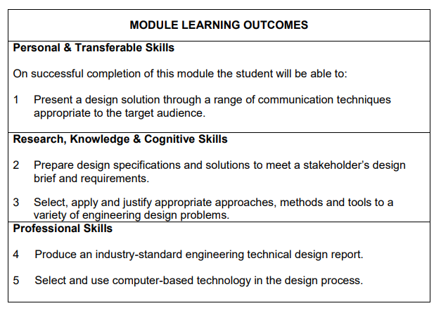
The assignment forms Element 2 of the module’s assessment criteria that covers Learning Outcomes 1, 4 and 5 as indicated below.
1 Following on from the first TMA in this module, produce a design report for one design of the product based on one of the scenarios covered on the
following pages. The report should contain, where appropriate:
• Title page
• Acknowledgements
• Summary
• Contents
• Introduction
• Basic Product Design Specification
• Design Parameters
• Simple Description of chosen Design
• Design Evaluation
• Detailed drawings of the design, including dimensions, such that its constructional features can be seen*
• Conclusions
• References
• Appendices
* Drawings should be submitted as complete engineering drawings done using CAD (or other suitable software). If the maximum size of printing is A4 then several sheets, each showing a different view of the design, will probably be needed to show sufficient detail for the design to be constructed. In this case, all views should be clearly labelled and all sheets numbered. Only computer-produced drawings will be marked; it is not acceptable to submit hand-drawn work. Please submit copies of the drawings within the report (.PDF) and in addition, upload the computer
files of the drawings (.DWG).
Note: you may have to invent information to make the design report complete.
SCENARIOS
Either
(a) Bicycle Rack
When a full design specification was produced and the weighted objective procedure carried out, it was found that a tow bar mounted rack was the best solution.
The rack is to bolt to the tow bar once the tow ball is removed. The dimensions of the tow bar bracket are shown in Figure 1. The 330 mm
dimension refers to the distance from the ground to the bottom of the bracket. In order to avoid the bikes fouling the car, it should be assumed that no part of either bike should protrude beyond the face of the tow bar bracket (ie between the bracket and the car).
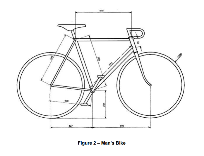
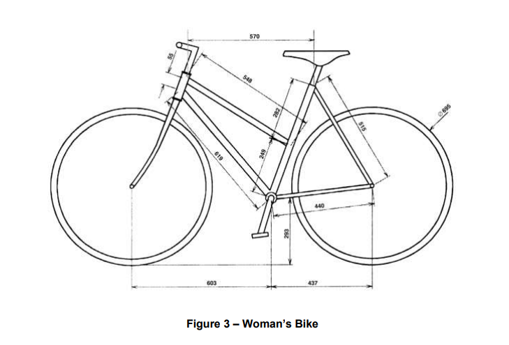
The two bikes to be carried have dimensions shown in Figures 2 and 3. The width of the handlebars of the man’s bike is 420 mm, whilst that of the
woman’s is 630 mm. The width across the pedals is 360 mm in both cases.
Your good friend Fred has offered to help build the bike rack and he has access to the following materials and equipment:
square section steel tubing, 25 mm × 25 mm × 2 mm thick
steel plate, 8 mm thick
steel strips, 25 mm wide by 6mm thick
brazing and welding gear
a powered hacksaw
a pillar drill
Design a suitable rack that can be made using Fred’s materials and equipment. It is not necessary to worry about stresses: the materials are
capable of exceeding the strength requirements of any design. In addition, the rack should be designed to ‘look right’.
As part of the report, you should produce:
(i) An arrangement drawing showing the outline of the bikes on the rack.
This does not need to be very detailed or show any dimensions but should clearly demonstrate that the rack will enable the two bikes to be
carried without fouling the car or the ground.
(ii) A detailed engineering drawing of the rack only, comprising front and side elevations with all dimensions required for manufacture shown.
OR
(b) Front Panel of Circuit Trainer An analogue/digital circuit trainer is required for open-learning students to use
to build circuits as part of their electrical/electronic practical work.
The circuits to be built can consist of up to five integrated circuits and their associated discrete components.
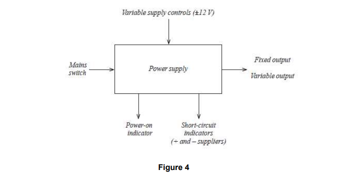
Figures 4, 5 and 6 show block diagrams for each system of the intended design.
(i) A power supply consisting of:
• 240 V supply input
• power ‘on’ indicator
• +5 V output
• +12 V output
• –12 V output
• 0 to +12 V variable output
• 0 to –12 V variable output
• output short-circuit indicators for ‘+’ and ‘–’ supplies
(ii) A function generator capable of:
• generating sinusoidal, triangular and square waveforms
• variable amplitude
• variable frequency
• frequencies in the ranges 0 to 100 Hz, 100 Hz to10 kHz and
10 kHz to 1 MHz’
(iii) A multimeter capable of measuring:
• resistance
• voltage
• current

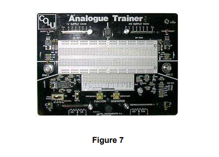
You will be required to draw a plan view of the front panel to show the mounting of the various controls, etc. A photograph of an example of an existing circuit trainer is given in Figure 7.
Answer

Do You Need Assignment of This Question