- ATHE Level 6 Unit 2: Assesses the impact of leadership and management skills and behaviours : Personal Leadership and Management Development Assignment, UK
- QUALIFI Level 5 Part 02 Unit 9500: A pilot Research Project is the small scale research project that is intended to highlight the pros: Research Project, UK
- QUALIFI Level 5 Part 01 Unit 9500: Research Project, UK Professional Development Academy
- You are to prepare a discussion paper aimed at the group of middle managers in your organisation : Personal Leadership and development, Assignment, UK
- Critically analyse the environment facing YourOrg, and identify the central issues confronting YourOrg resulting : Strategic Management Assignment , CMU, UK
- Unit 15: This assignment requires you to analyse, design, develop, and evaluate an Internet of Things (IoT) application: Transport Network Design (L5), Assignment BTEC, UK
- Clearly differentiate the terms organisational mission, vision and strategy: Strategic Leadership And Management In Context, Assignment, UK
- ATHE Level 7 : Understand the importance of financial data in formulating and delivering business strategy : Finance for Strategic Managers, Assignment UK
- CMI Unit 703 : Collaboration and partnerships can turn ideas into reality, enhancing opportunities for innovation and creativity, research and development : Collaboration and Partnerships, Assignment, UK
- 7OS01- Explain how the Employment Tribunal, the County Court, The Health and Safety Executive and the Information Commissioner : Advanced employment law in practice, Assignment, UK
- ILM 308 – Describe the factors that will influence the choice of leadership styles or behaviours in workplace situations: Understanding Leadership Level 3 Assignment , UK
- Level 5 CMI Unit 526 – Mark Sheet: Principles of Leadership Practice, UK
- Level 5 CMI Unit 526 : Understanding of ethical leadership and the impact of culture and values on leadership- Principles of Leadership Practice, Assignment, UK
- CMI Unit 501: Examine the impact of legal status on the governance of an organisation- Principles Of Management And Leadership In An Organisational Context Level 5 Assignment, UK
- ILM Level 5 Effective Communication Skills, Assignment , UK
- ILM Level 3 – Describe the factors that will influence the choice of leadership styles or behaviours in workplace situations Referral : Understanding Leadership styles, Assignment, UK
- CMI Unit 502 Understand approaches to developing, managing, and leading teams: Principles of Developing, Managing and Leading Individuals and Teams to Achieve Success, Assignment, UK
- R033 Supporting individuals through life events, Set Assignment, OCR, UK
- Working in partnership in health and social care, Assignment, UK
- CMI Unit 5034 Problem solving tools and techniques for consultants, Assignment, UK
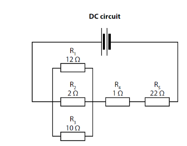
The diagram shows a DC resistor network. The network is supplied by a 12 V battery: Unit 57 – Electrical and Electronic Principles Assignment, UK
| University | University of Plymouth(UoP) |
| Subject | Unit 57 – Electrical and Electronic Principles |
ACTIVITY 2
1. The diagram shows a DC resistor network. The network is supplied by a 12 V battery.
Using the information in the network diagram, calculate:
(a) the current flowing through resistor R5
(b) the overall power dissipated in the network.
Buy Answer of This Assessment & Raise Your Grades
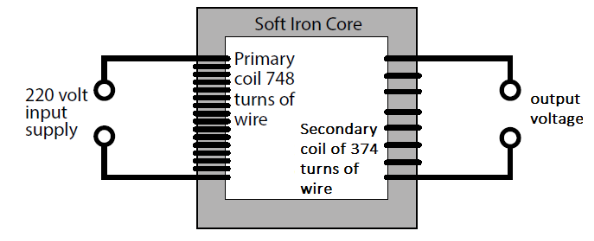
2. A transformer is used to provide an AC supply to a piece of portable equipment.
(a) Calculate the peak value of the input supply.
(b) Calculate the output voltage from the transformer and then draw a waveform to represent the output voltage over two cycles.
You should indicate the amplitude and the time period on the waveform.
(c) A technician checks the operation of the transformer. The calculations show that the transformer is 93% efficient. Use this information to calculate the actual output voltage from the secondary coil.
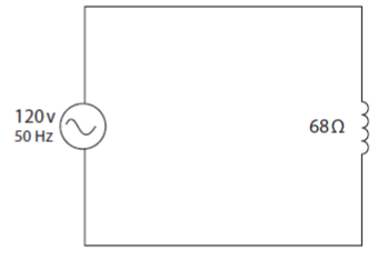
3. An electrical engineer has connected a coil to a 120 V AC supply at a frequency of 50 Hz.
0.75 C of charge passes through the coil in 5 minutes.
(a) Calculate the current passing through the coil.
The coil has an internal resistance of 68 ohms.
(b) Calculate the inductance of the coil.
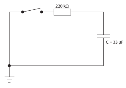
The diagram shows a fully charged capacitor that is discharged through the resistor when the switch is closed.
(c) Calculate the time constant of the capacitor.
When the capacitor is fully charged and t = 0, the voltage across it is 16 V.
(d) Calculate the voltage across the capacitor after 12 seconds.
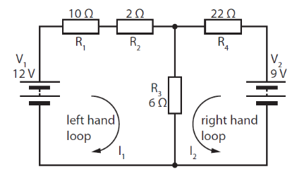
4. The diagram shows a resistor network with two power supplies.
V1 is supplied from a variable power supply that is supplied with a current of 1.1 amps.
(a) Calculate the power drawn by the power supply.
(b) Calculate the current flowing through resistor R3.
(c) The supply voltage V2 is increased to 15 V. Explain how this would affect the current flowing through resistor R3.
Are You Looking for Answer of This Assignment or Essay
Struggling with your Unit 57 – Electrical and Electronic Principles Assignment? We’re here to help. Our platform specializes in assignment writing services designed for UK students. With our expert team, you can tackle all types of assignments challenging with confidence. buy any service at a cheap rate like an essay, coursework, homework writing service, and many more.

